LEGO Robotics microcontroller control - NXT touch sensor
Introduction
LEGO and LEGO Technic have had many different systems for robotics, sensors, and actuators over time. In our house, we have Mindstorms NXT and BOOST, and I also have access to Mindstorms EV3, Spike Prime, and Power Functions. During this post series, I want to explore how these sensors and actuators communicate using different microcontrollers, and at the end, maybe end up with something that can use all the different sensors and actuators I have from different systems.
Mindstorms NXT/EV3 Connectors
We first tackle the Mindstorms NXT sensors and actuators, so we need to be able to connect to them. NXT and EV3 both use custom connectors that are modified RJ12 connectors with the plastic pin to hold the plug in the socket moved slightly to one side compared to standard RJ12 connectors. Connectors, plugs, and cables can be bought from Mindsensors (Sockets, plugs) and from AliExpress. For my experiments, I chose to cut an NXT cable in two, strip and tin the wires from one half, and insert them into a breadboard while I wait for the sockets I ordered to arrive.
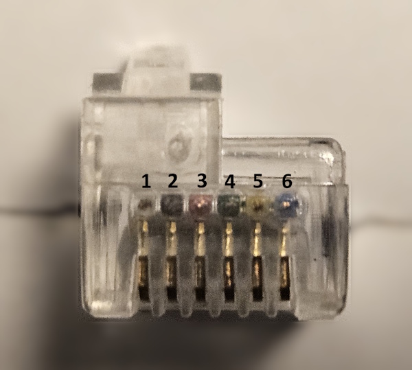
The connector has six pins numbered from 1 to 6. The original NXT cable is color coded with the following colors:
| Pin number | Color |
|---|---|
| 1 | White |
| 2 | Black |
| 3 | Red |
| 4 | Green |
| 5 | Yellow |
| 6 | Blue |
The following picture shows the plug with the pin numbers:
Connecting the cable to the Nano
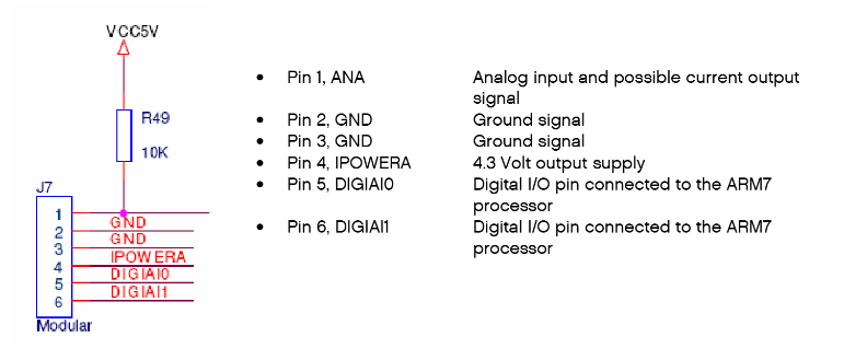
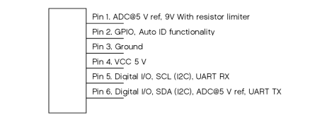
As the first peripherals we try to use are the NXT basic sensors, we just look at the input port and ignore the motor port for now. The input port pins are defined as follows in the NXT and EV3 Hardware Development Kits:
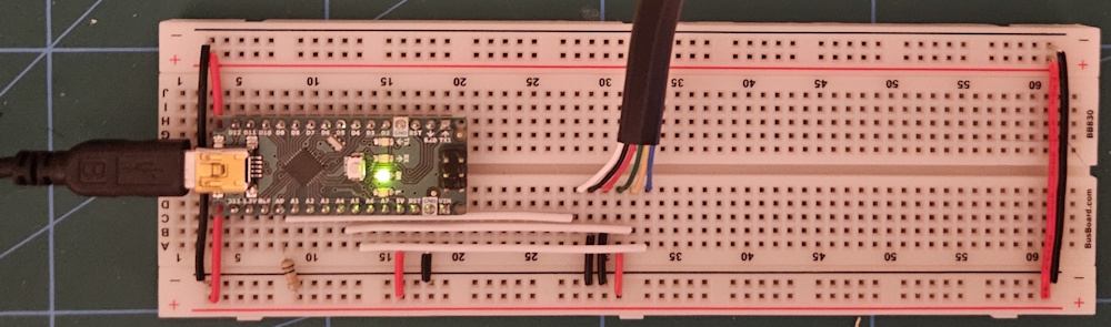
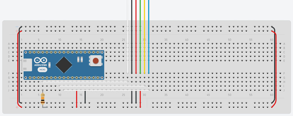
As a start, we connect the cable to the Arduino Nano based on the NXT description. As we add support for more peripherals, this will change, but this is a good starting point. We connect the cable to the Nano in the following way:
| Pin number | Connected to |
|---|---|
| 1 | AO on the Nano, with a 10k pull-up resistor to VDD (5V) |
| 2 | GND |
| 3 | GND |
| 4 | VDD (5V) |
| 5 | A4 on the Nano |
| 6 | A5 on the Nano |
NXT basic sensors
We start with the basic (non-I2C) sensors from my old Mindstorms NXT set. The NXT Hardware Developer Kit lists two types of non-digital sensors, active and passive. The active sensors are all sensors from the earlier Mindstorms RCX sets that are still supported on NXT, so we only look at the passive sensors. My NXT set came with three passive sensors: a touch sensor, a light sensor, and a sound sensor. At the end of this post, we should be able to use all three of those sensors using an Arduino Nano. For later parts of the series, I might switch to more advanced microcontrollers, but for now, we stick with the Arduino Nano.
Touch sensor
The simplest sensor in the NXT set is the touch sensor. Looking at Appendix 5 in the NXT HDK, we see that this sensor consists of a simple momentary switch connected between pin 1 on one side and pins 2 and 3 on the other side, with a 2k2 ohm resistor on the other side:
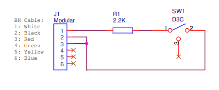
This means that when the touch sensor is not pressed, the switch is open and pin 1 is pulled up to 5V via the 10k pull-up resistor. When the sensor is pressed, the 10k pull-up resistor and the 2k2 resistor form a voltage divider. Calculating the voltage at pin 1 with VDD at exactly 5.0V gives us 902 mV. Looking at the EV3 HDK auto ID table, we see that the EV3 brick detects an NXT touch sensor when pin 1 voltage is between 850 mV and 950 mV. We use the same values for our code. We also detect an open switch if the value is above 4.8V. Any value in between these values is probably during transition or switch bounce, so we ignore those.
Super simple code for reading the sensor, without any debouncing, etc.:
#include <Arduino.h>

#define MS_INPUT_PIN_1 A0  // PIN 1: Analog input with external 10k ohm pull-up resistor to 5V

enum SensorState {
  SENSOR_RELEASED = 0,
  SENSOR_PRESSED  = 1
};

int touchSensorStete = SENSOR_RELEASED;

void setup() {
  pinMode(MS_INPUT_PIN_1, INPUT);         // Use external 10k ohm pull-up resistor to 5V
  Serial.begin(9600);
}

void loop() {
  // Simple touch sensor logic using analog read on pin 1
  // No button debouncing for simplicity, need to be added for real applications
  int pin1Voltage = analogRead(MS_INPUT_PIN_1) * (5.0 / 1023.0) * 1000; // mV
  int newTouchSensorState = touchSensorStete;

  if(pin1Voltage > 850 && pin1Voltage < 950) {
    newTouchSensorState = SENSOR_PRESSED;
  } else if (pin1Voltage > 4800) {
    newTouchSensorState = SENSOR_RELEASED;
  }

  if(newTouchSensorState != touchSensorStete) {
    touchSensorStete = newTouchSensorState;
    if(touchSensorStete == SENSOR_PRESSED) {
      Serial.println("Touch Sensor Pressed");
    } else {
      Serial.println("Touch Sensor Released");
    }
  }
  delay(100);
}
Next post
For the next post in the series, we implement the rest of the basic NXT sensors and start making the code into a real library that can be used for different projects.
Source code
The source code for this post can be found at GitHub: https://github.com/vegardw/lego-robotics-control/tree/v0.1
Resources and references
- Using NXT Components With a Micro Controller - An instructable on how to use the NXT sensors using the Basic Stamp microcontrollers. Used for info on pin outs and protocols for the different sensors and motors.
- LEGO Mindstorms NXT Hardware Developer Kit - The Mindstorms NXT HDK